

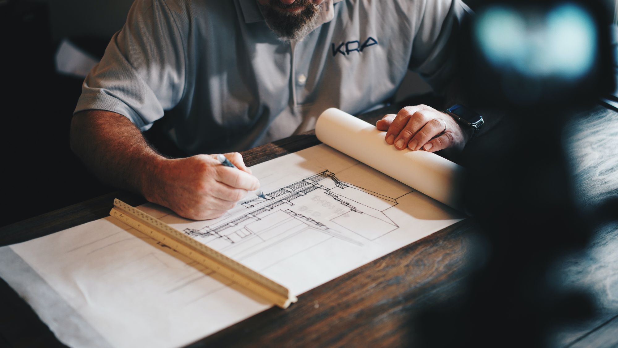
It can be overwhelming to learn how to interpret a manufacturing blueprint because there is so much material to absorb. Knowing what to look for and what those components represent is crucial when interpreting a manufacturing blueprint.
Manufacturing blueprints are illustrations created to aid the reader in understanding how to create and operate a specific product or device.
Blueprints are made manually or with the help of specialist software by a draftsperson or designer. They create designs according to a specific scale, therefore the blueprints are either considerably smaller or much larger than the final product.
A blueprint's sole function is to display all of a part's specifics. Imagine that a drawing would effectively describe and show all the specifics of how to hold a single part in your hand if you were holding it in your hand.
ERP.AI supports manufacturers by integrating blueprint specifications directly into production workflows, ensuring every department—from procurement to assembly—follows the same detailed plan without discrepancies.
This article will guide you with reading a manufacturing blueprint step-by-step.
Manufacturing Blueprints
Drawings and designs created for the purpose of directing the building and manufacture of a product make up manufacturing blueprints.
These blueprints offer a planned procedure, requirements, standards, etc. that, if followed, will result in the development, building, or production of a gadget or product. Engineering blueprints are a vast category of drawings that includes manufacturing blueprints.
- Manufacturing Blueprint is a type of intangible asset that, according to the science of business valuation, has the potential to bring its owner financial rewards.
- Business valuation analysts use approaches under the market, asset, and income valuation methods to determine the fair market worth of manufacturing designs.
- A flat table and a reading light should be used to lay down the production layout.
- In low light, many designs are difficult to read because of their thin lines. In case you wish to take notes, keep paper and a pen nearby. Note the tolerance that the blueprint is allowed for.
- The amount of difference between the scale of the blueprint and the manufactured product may exist, and this is referred to as tolerance.
Components of a Print
Information Blocks
In order to tell the reader who the print belongs to, the part number and description, as well as details about the material and finish, engineers insert a lot of important information in the blocks. The drawing's bottom right corner is where the information blocks are situated.
When the information in a block is unnecessary or hasn't been decided, it may occasionally be left empty. From the perspective of manufacturing, the more information the better, and all of the blanks should be filled in to prevent assumptions. These are some of the information blocks:
Title Block
The title block, in the lower right corner of a blueprint, contains the following information:
- Name: Who created or owns the drawing, a firm or organization.
- Address: Location of the business or organization.
- Name and date: Engineers in charge who created, reviewed, and approved the drawing.
- Part name/description: Explains what the component is.
- Part/drawing number: Given number to identify the component.
- Revision: Determines which drawing is the correct one.
- Scale (optional): The ratio of the part's real size to its size on the design. You can write it out as 1:1 or 1=1. The first number refers to the part's real size, whereas the second number denotes the print. In other words, 1:2 denotes a print size that is twice the actual size. Whereas 3:1 denotes that the size is actually three times what is depicted on the poster.
- Size: The dimensions of the sketch.
Revision Block
A revision block is present in the top right corner in addition to the revision that is depicted in the Title Block. The Revision Block provides information about the particular modifications that were performed to roll the revision.
The revision, a summary of the changes made, the revision date, and the revision's approval are all included in the revision block.
Bill of Materials (BOM) Block
A Bill of Materials Block, which contains a list of every item required for the project or assembly, is present for parts that need to be assembled, need hardware to be added to the part, or are kits of parts.
The acronym BOM, which can be pronounced as "bomb," stands for "Bill of Materials," "Parts List," or "Schedule." The BOM contains the item's part number, name or description, material specification (if applicable), and quantity needed for that item.
On the print, the BOM can be found in a number of places. The two most typical placements are directly above the Title Block or in the upper left corner.
Lines
It's important to understand each type of line and what it implies. Three different types of lines exist:
- Centerlines: designed to display the exact geometric centre of the assembly. They consist of a series of progressively longer and shorter dashes.
- Hidden line: Indicates an edge that is concealed behind a face.
- Phantom line: frequently used to depict a moving object in a distinct setting. This symbol is also used to represent a break when an obstruction prevents the usage of a conventional type of break.
- Visible line: The right perspective makes an edge visible.
Application Block
The larger unit that contains the part or assembly on the design is identified either directly or by reference in the application block on a blueprint for a part or assembly.
The drawing number or model number of the following larger assembly, of which the smaller unit or assembly is a component, will be listed in the next assembly (NEXT ASS'Y) column. The model number or equivalent identifier of the component of the assembled unit is displayed in the USED ON column.
Tolerance Block
The tolerance block, also known as the general tolerance block, is typically found in the bottom middle or bottom right corner of the layout. Tolerances for dimensions that aren't explicitly mentioned on the drawing are identified in the tolerance block.
This can apply to criteria for surface roughness or the dimensions units (metric or imperial) of the plan.
Measurement Units
The print's units are crucial because there is a significant difference between 25.4mm and 25.4 inches. The measurement units are frequently noted in the title block or tolerance block, but they may also appear in other places in the plan, such as the notes.
Although angular units are as significant, there is typically less ambiguity surrounding them due to the differences between decimal degrees and degrees, minutes, and seconds.
Types of projections
Different representations of parts on a blueprint are called projections. This basically means that the same part can be shown in many ways.
- First angle projection, often known as the European convention, is a technique for showing the different views of the part as though it had been turned on its side.
- The American convention of third angle projection involves showing the part's numerous views as though it were put in a bowl and rolled to the other viewpoints.
- It might be challenging to put projections into words. Just keep in mind that the first angle projection method is a flop method and the third angle projection method is a roll method.
Types of tolerances
A dimension can be tolerated in a variety of ways. The methods for directly dimensioning a feature with standard tolerances are listed below. Tolerances for GD&T are a completely different subject.
- Limit tolerances: Limit tolerances specify an acceptable range for the dimension. No computation is required. Just keep it within the range.
- Unilateral tolerances: When the permitted variation can only occur in one direction, as in the example below, unilateral tolerances are used. In this case, the component's diameter cannot be greater than 6 mm.
- Bilateral tolerances: Bilateral tolerances have a nominal size and a tolerance in both the positive and negative directions. They are frequently referred to as plus or minus tolerances. This tolerance doesn't have to be equal in both directions, but it frequently is. Bilateral tolerances that permit larger fluctuation in one direction are occasionally seen.
Zone Letters and Numbers
Between the red lines, prints have a border all the way around them that includes letters and numbers. In order to locate and identify specific regions of a print, these letters and numbers are employed as a kind of map.
From the bottom to the top, the letters are arranged alphabetically. From right to left, the numerals are arranged in numerical sequence. You must read the zones from right to left as a result.
Notes and Specifications
Since the component is depicted visually and in dimensions on the blueprint, there are frequently additional details about the part that cannot be seen graphically but are provided in the Notes and Specifications, which are usually found in the upper or lower left corner of the blueprint.
Notes are more details regarding the part. Specifications, on the other hand, refer to a real document or statement that outlines how the parts are to be produced, put together, and maintained.
Steps Involved in Reading Blueprints
The drawing is the most significant component of a manufacturing print. The ability to picture the drawing is the most crucial aspect of print reading. Knowing what the actual component will look like requires the capacity to mentally visualise the part from the drawing.
Before a part can be created from a print, a manufacturer must envision it. An inspector often examines a part after it has been manufactured to ensure that it complies with the drawing. The actual part and the drawing must match.
Find the information blocks and read them.
The title and revision blocks, which make up the majority of the blueprint's identifying data, are among these blocks.
- The information blocks include all of the blueprint's identifiers, such as the component's name, surface texture, and intended usage, as well as the blueprint number or part number that corresponds to the component and the business or engineer that created it.
- Along with the reference and zone numbers that specify the location of the part's intended use when it is built, they also provide the revision number for the blueprint.
- In addition to the other information blocks, a scale block may also provide scale information.
Check out the material list.
The manufacturing blueprint should have this list on the first page. The components and equipment needed to properly build each component shown on the plan are listed in the materials list.
Find the key.
The key to a manufacturing blueprint can be found close to the edge of the page, much like the legend on a map.
- The key will include the scale at which the plans were made as well as any additional details about how to interpret them, such as measurements and an explanation of any symbols that were used.
- Additionally, it provides a list of the acronyms used in the plan along with their definitions.
- In some circumstances, the key and additional information about the drawing will be on the front page of the blueprint.
Analyze the plans as a whole.
It is necessary to be familiar with the component being developed and built in order to comprehend the detail in the blueprints. Try to comprehend how the diagram's bigger components fit together by first analyzing them.
Examine the blueprint's specific details.
After becoming comfortable with the main portions of the plan, pay close attention to the drawing's smaller and more intricate aspects. These particulars will be an essential component of the component's manufacturing process.
Study the lines.
The majority of a blueprint's elements are drawn lines.
- Every line type has a distinct meaning.
- A visible edge of the finished component, for instance, is indicated by a thick solid line.
- An inner border of the finished component that cannot be seen from the exterior is denoted by a dotted line.
- Thin lines that repeat long and short dashes are used to represent where the centre of parts of the component is located, whereas lines that finish in arrows are used to indicate a certain distance.
5 Benefits of Manufacturing Blueprints
Why is a correctly designed drawing package necessary for the production of any product? Simply put, since bad drawings waste a tonne of time and money!
Simpleness of switching manufacturers
Any manufacturer should be able to understand a professional manufacturing blueprint. This implies that the identical blueprints can be given to a different manufacturer so that production can continue even if a manufacturer consistently provides inferior parts, consistently misses deadlines, or raises prices.
Another reason not to let the manufacturer develop the production blueprints is that they might use domestically developed blueprints as a bargaining chip, demand exorbitant prices in exchange for the drawings, or even assert design ownership. This frequently forces consumers to work only with producers, who can then choose the terms of their cooperation.
Improved communication
The maker and the owner of the product can communicate via a manufacturing blueprint. As a result, it must explain the design objective to the manufacturer in a way that they can easily comprehend.
- Manufacturers may fill in the gaps with their own standards or prior expertise if any crucial information is omitted. This could be a challenging scenario because the manufacturer may not always be aware of the entire breadth of the design or how the part will work with other parts or machinery.
- To avoid any uncertainty, a technical blueprint that is clear and professional provides all the pertinent production details.
- The best of both worlds is offered by detailed part blueprints mixed with a 3D overview: enough detail to make the parts correctly and enough visual context to help with comprehending the wider picture.
Shortened manufacturing period
Professional manufacturing blueprints may drastically cut down on manufacturing time and eliminate the need for error-correcting time.
- If a manufacturer receives subpar designs, they may need to make their own shop drawings to enable their staff to produce the parts. Due to the manufacturer's need to figure out how everything fits together on their own and the likelihood that customers will ask numerous questions along this process, there will be significant delays.
- Even worse, if the manufacturer does employ the subpar designs, the parts and product will be incomplete, with incorrect sizes, finishes, fits, and other flaws brought on by subpar drawings, which can then take weeks or months to fix.
- Every time a clarification on a drawing is required, time and money are lost.
- To clarify something that could have easily been included in the sketch, both the manufacturer and the consumer will need to put off their current plans.
New product designs
A new product's design set must be updated to reflect any modifications that may have been necessary for production or functionality beyond the prototype stage.
- Up to date blueprints can be crucial if redesigns are required as a result of field performance evaluations.
- A proper drawing set will spare time on pointless repetition of labour for the upcoming version of the product.
- Making revisions to a product could be impossible because of a subpar drawing set, missing digital data, or a designer you can't get in touch with. Sometimes the only way to proceed is to recreate the complete drawing bundle.
- A professional set of drawings can help you save a tonne of time and money in the long run in addition to providing you with a first-rate design.
Enhanced quality control
Maintaining product consistency and compliance depends on quality control.
- Inspection and test checklists are used in conjunction with manufacturing drawings to hold manufacturers accountable and to convey requirements clearly.
- Any time a component requires a particular tolerance (such as when it must fit with other components or machinery), the calculation must be accurate and the tolerance must be noted explicitly on the blueprint.
- The part is approved by the QC representative of the manufacturer after they have verified that it complies with the tolerances listed on the drawing.
- Without correct tolerance information, a manufacturer may be pushed to adhere as closely as possible to every dimension of a drawing; they may think that these dimensions will serve as a benchmark for whether to accept or reject items. Or, they might think certain dimensions are insignificant, which would require expensive revision.
- In order to enable the quickest and least expensive manufacture, a smart designer will have determined the most forgiving tolerance for a specific item or function.
- High precision measurements that are unnecessary (but sometimes added by default to speed up design) increase costs and cause confusion.
- Extreme precision lengthens the time required for machining operations, which can cause prices to rise significantly. This cost overrun is particularly typical in the case of machined components.
To ensure that the manufacturer can work efficiently and offer feedback for quality control, dimensions and tolerances must be accurate. Other details, such as material and finish comments, or information particular to a process, such as weld standards or assembly instructions, must also be included in the designs for the product to be consistently produced at scale and over time.
The following are some crucial areas where an ERP or MRP (Material Requirements Planning) system can be helpful in:
- Monitor carrying costs
- Control production
- Evaluate work-in-progress costs
These solutions allow you to quickly view your manufacturing and material expenses. This simplifies your selling price computation in the end.
Filing and Handling Blueprints
The way prints are folded is determined by the kind and size of the filing cabinet as well as the location of the identification marks on the prints.
When filing prints vertically (upright), it is advisable to place the identifying marks at the top; when filing flat, they should go in the bottom right corner. Rolls may occasionally be used to store construction prints.
Permanent records like blueprints are useful. But you must take special care with them if you plan to maintain them as permanent records. Here are some basic guidelines that will be useful.
- Maintain proper storage of prints.
- Refold prints that are incorrectly folded if you receive them.
- Prints should be kept away of direct sunlight as they fade.
- Avoid letting prints get wet or get grease or oil on them.
- The prints may become unreadable as a result of those materials' inability to fully dry out.
- Never annotate a print with a pencil or crayon without getting permission.
- If you are told to annotate a print, make the annotations a permanent part of the print using the appropriate colored pencil.
- A blue background print looks good with the hue yellow (blueprint).
How AI Improves Manufacturing Processes
AI systems help streamline operations by monitoring equipment performance, detecting inefficiencies, and predicting maintenance needs before breakdowns occur. AI-powered solutions unifies production data, allowing manufacturers to forecast demand, optimize resource allocation, and reduce waste.
By automating routine tasks and enabling real-time decision-making, AI empowers manufacturers to boost productivity, improve traceability, and stay compliant with regulations—ultimately driving faster, safer, and more efficient production lines.
How can Deskera Help You?
As a manufacturer, you must keep track of your inventory stock. The condition of your inventory has a direct impact on production planning, people and machinery use, and capacity utilization.
Deskera MRP is the one tool that lets you do all of the above. With Deskera, you can:
- Control production schedules
- Compile a Bill of Materials
- Produce thorough reports
- Make your own dashboard.
Deskera ERP is a complete solution that allows you to manage suppliers, track supply chain activity in real time, and streamline a range of other company functions.

Deskera Books allows you to manage your accounts and finances better. It helps maintain good accounting standards by automating billing, invoicing, and payment processing tasks.
Deskera CRM is a powerful tool that organizes your sales and helps you close deals rapidly. It enables you to perform crucial tasks like lead generation via email and gives you a comprehensive view of your sales funnel.
Deskera People is a straightforward application for centralizing your human resource management activities. Not only does the technology expedite payroll processing, but it also helps you to handle all other operations such as overtime, benefits, bonuses, training programs, and much more.
Key Takeaways
- Instructions for manufacturing are found in blueprints.
- Blueprints originate in the engineering division and provide the manufacturing division with all the data required to produce a product. Dimensions, part names, and other information are all included.
- A manufacturing engineer can begin the production process without hesitation as soon as he receives the drawing.
- To ensure that all measurements are measured accurately and that tolerances are adhered to to the smallest detail, measuring equipment must be kept calibrated.
- Remember that every blueprint has a series of meticulously planned, logical phases while learning how to interpret one.
- Symbols and lines used in blueprints have very particular meanings, and drawing pages in sets of blueprints are organized in a predictable way.
- The universal language of manufacturing is blueprinting because measurements are everything. Accuracy is ensured by reading it and correctly implementing it in your operations, which leads to satisfied clients and suppliers. The equivalent of not understanding the language in a strange country is not being able to read blueprints.
- Remember that it could take a while to understand an engineering drawing, depending on the complexity of the assembly and the reader's level of experience.
- If you want to learn more, seek for a course that will instruct you on how to correctly read and interpret drawings and give you a better understanding of the unique requirements of a project. You can choose to browse for engineering services nearby if you're also interested in professional drafting services.
Related Articles